
The Impact of Circularly Polarized Antennas

An individual bay, ready to be installed.
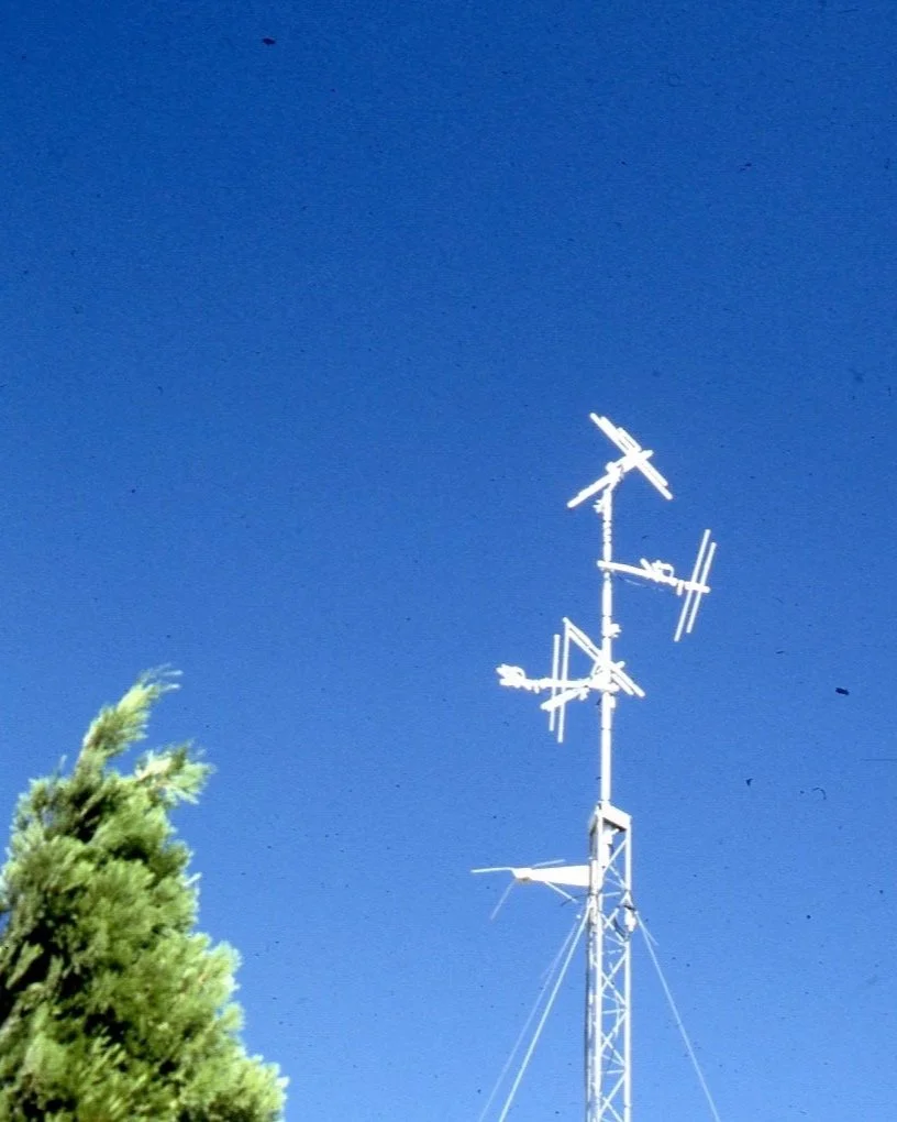
The finished, 4-bay antenna, mounted on the tower.
Pioneering Circularly Polarized Antennas in the RF Industry
Back in the late 1970’s, when I was just getting started in the RF industry, I was mentored by a good friend and Ham Radio buddy named Ray. Ray was an RF engineer who specialized in antenna design, and worked for a defense contractor that made a variety of sophisticated antennas for military and space applications.
Being an experimenter, I had built a Ham Radio repeater station and located it on top of a 4000’ peak at the edge of the San Fernando Valley. The coverage was great, but there were a lot of areas that were slightly shadowed by the surrounding hills, and the signal in those areas was pretty marginal.
Ray was one of the Hams that used my repeater, and he took note of the coverage issues. One evening, as we chatted about improving the system, Ray told me that I should consider using a circularly polarized (CP) antenna. I knew a little about CP, that it had been developed for use with spacecraft, since in space the idea of vertical or horizontal makes little sense, since there is no “up” or “down.”
Collaborating with an Expert Antenna Designer
Why would CP help, I wondered aloud? Ray explained that when you get into RF environments that are not a clear path, the polarization of a radio signal can be “rotated” to a different plane than the original, due to reflection or refraction or a combination of both; a phenomenon known as “polarization rotation.” This means that a signal from a vertically polarized antenna at the radio site winds up being horizontal at the user’s radio location. When the polarizations are mismatched, a substantial loss of signal occurs, typically on the order of 20 dB. This is what caused the signal degradation in the marginal coverage areas of my repeater. With a circularly polarized antenna, when the wave signal is rotated due to reflection or refraction, it’s still circularly polarized, and so doesn’t have the loss that a linearly polarized signal would.
Ray offered to help me build a circularly polarized antenna. When an experienced antenna designer offers to help you build an antenna, how can you say no? In a matter of a few weeks, we had built a huge monstrosity of an antenna, and we were ready to install it at the radio site. In the spirit of true experimenters, we decided to leave the old antenna up and put the new one just below the old one. We added a remote-controlled antenna switch, and told all of the users on the repeater to “pick the antenna they liked the best.” We had a simple strip chart recorder that kept track of which antenna was being used.
The results were stunning. Not only was the CP antenna almost universally chosen, but the comments from the other Hams using the system were overwhelmingly in favor of the new antenna. It wasn’t long before we took down the old antenna, and left the CP antenna as the only option.
Enhancing Wireless Coverage with Circularly Polarized Antennas
Since then, I have noticed several places where CP antennas have made their mark. FM radio stations almost all use CP antennas, and my friends in the broadcast industry tell me that without circular polarization, FM would never have been as popular as it is today. Also, as it turns out, the wireless microphone and intercom industry uses CP extensively to prevent coverage-related noises and dropouts.
Until recently, most CP antennas (other than those used for FM broadcasting) were for the UHF (ultra-high frequency) band, as VHF (very high frequency) CP antennas were too large and unwieldy for a lot of applications. That has all changed with the introduction of our CP-1V, a compact, circularly polarized antenna that covers the entire high VHF band from channel 7-13 (174-216 MHz) and can be used for intercoms, IFBs, in-ear monitors, and VHF wireless microphones, all in a compact 18 by 18-inch package. If you’re having coverage issues at VHF, check out more details below!

The CP-1V VHF antenna is a leap forward in RF technology. It occupies a small footprint of 18 inches square, but performs more effectively than much larger competitors. It is a true circularly polarized antenna, and covers the entire VHF wireless IEM/microphone/intercom band.
In performance tests, the CP-1V antenna exhibited fewer dropouts and greater overall range. Its rugged construction makes it suitable for both indoor and outdoor use, including hilltop translator use. While not a high power transmit antenna, it handles enough power to make it practical for multi-transmitter VHF in-ear monitor systems.
SUGGESTED USES
VHF wireless microphone receivers
VHF IEM and IFB transmitters
VHF wireless intercom systems
VHF television off-air monitoring
VHF television translator receive antennas
VHF television CATV head-end antenna
SPECIFICATIONS
SWR: Nominally 2:1 or better over the entire band, 174-216 MHz.
Power handling: 5 watts.
Gain: 3 dBd, circular.
Cardiod pattern, -3 dB beamwidth: Approximately 100 degrees.
Front to back ratio: Approximately 20 dB.
The success of the CP-1V has led us to start development on a UHF version as well. Sign up for our newsletter to be among the first to know when it’s available.